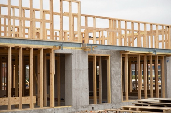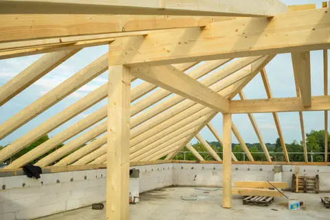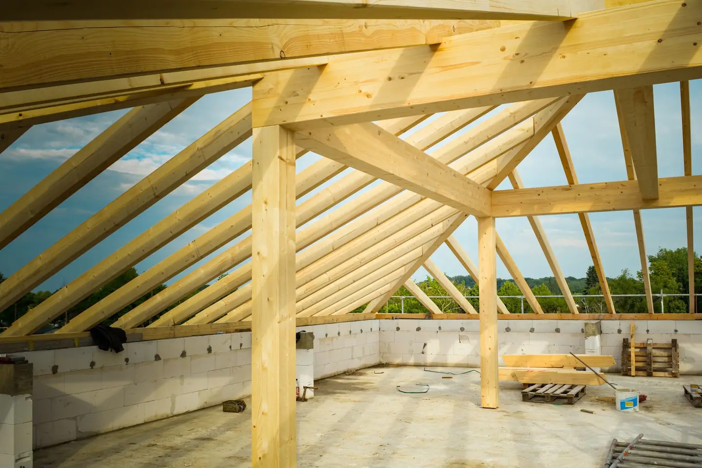
Getting joist sizing right is fundamental, undersized or incorrectly spaced joists lead to springy, noisy floors, plaster cracking, and in extreme cases, structural failure. Building Regulations Part A (Structure) requires joists to be engineered for the applied loads, and the TRADA span tables that Approved Document A points to provide the starting point for most domestic sizing decisions.1
This guide covers the most common solid timber and I-joist scenarios. For unusual spans, point loads, or notching and drilling requirements, commission a structural engineer.
Common Joist Sizes
Solid timber joists are typically regularised C16 or C24 graded softwood (spruce, pine or fir) supplied in the following cross-sections (all in mm width × depth):
- 47 × 100 mm
- 47 × 125 mm
- 47 × 150 mm
- 47 × 175 mm
- 47 × 200 mm
- 47 × 220 mm
The 47 mm width is the regularised standard; 44 mm and 50 mm sections also exist from some suppliers but 47 mm is most common in the UK. Joist depth drives span capacity, width contributes to stability, not primarily to bending strength.
Timber grade matters significantly. C24 has a characteristic bending strength of 24 N/mm² versus C16 at 16 N/mm².2 This means C24 achieves the same span with a shallower section, or a longer span at the same section. Most UK suppliers now stock C24 as standard; confirm the grade on your delivery note.
Span Basics
Indicative maximum spans for domestic floor joists (imposed load 1.5 kN/m², dead load up to 0.5 kN/m²) using C24 solid timber at 400 mm centres:3
| Joist size (mm) | Max span (approx.) |
|---|---|
| 47 × 100 | 1.8 m |
| 47 × 125 | 2.3 m |
| 47 × 150 | 2.8 m |
| 47 × 175 | 3.3 m |
| 47 × 200 | 3.8 m |
| 47 × 220 | 4.3 m |
| 47 × 225 | 4.5 m |
These are rough, conservative figures. Timber Development UK’s C24 span table is the reference to use: it gives, for example, 4.13 m for a 45 × 195 mm joist at 400 mm centres with a dead load up to 0.5 kN/m².3 Actual spans depend on load condition, board type (tongue-and-groove deck or loose), point loads from partitions and services, and notch or hole positions. Always consult the full span table or a structural engineer for actual specification.
For roof rafters (which carry lower imposed loads: Timber Development UK’s tables use 0.6 kN/m², or 1.02 kN/m² where snow loads are higher), the same section sizes span farther. A 45 × 170 mm C24 rafter at 400 mm centres spans about 3.6–4.15 m in those tables for roof slopes of 30 to 45 degrees, depending on the weight of the roof covering and the snow load.3 Refer to Timber Development UK’s span tables for rafters.
Spacing: 400 mm vs 600 mm
Joists are typically installed at 400 mm or 600 mm centres, measured from the centre of one joist to the centre of the next.
400 mm centres: the standard for domestic floors. Provides a stiffer floor with less board bounce, suits standard 18 mm T&G chipboard or plywood decking, and distributes loads well. Preferred under kitchen units, bathrooms, and anywhere a point load from a partition or bath may occur.
600 mm centres: needs about a third fewer joists but requires a deeper joist section to achieve the same span and stiffness. Chipboard decking has to go up from 18 mm to 22 mm, because 18 mm chipboard is rated for joists up to 450 mm apart.4 More commonly used in roof construction (rafters and ceiling joists) where imposed loads are lower.
A simple rule: if you increase joist spacing from 400 to 600 mm, you generally need to move up one or two depth sizes to maintain the same span. The saving in joist count is partly offset by the cost of deeper sections.
Strutting and Noggins
Lateral stability of floor joists is as important as span capacity. Without strutting, joists can twist under load, causing creaking floors and potential loss of composite action with the deck.
Herringbone strutting: traditional timber noggings fixed in a cross-brace pattern between joists. Required at mid-span for spans over 2.5 m, and at third-points for spans over 4.5 m.4 Members should be at least 38 × 38 mm, and herringbone strutting should not be used where the gap between joists is more than about three times the joist depth.4
Solid blocking (solid strutting): solid timber blocks between joists, at least 38 mm thick and at least three-quarters of the joist depth, typically at mid-span or where joists frame into steel beams.4 More resistant to racking but uses more timber.
Metal herringbone strutting: proprietary galvanised steel strut. Faster to install than cut herringbone and widely used in new build. Install per manufacturer’s instructions.
Warranty standards call for it too: LABC Warranty’s technical manual requires strutting on any floor joist span over 2.5 m.4
| Joist span | Strutting requirement |
|---|---|
| Up to 2.5 m | None required |
| 2.5 m to 4.5 m | One row at mid-span |
| Over 4.5 m | Two rows at third-points |
| I-joists | Same spans and rows as above, plus any blocking the manufacturer specifies |
I-Joists vs Solid Timber
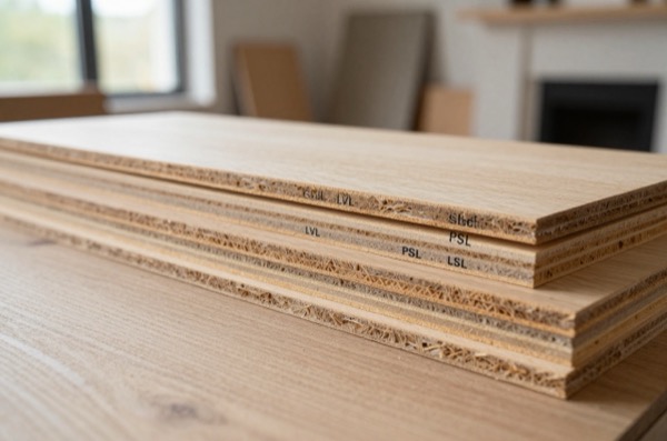
I-joists (engineered wood I-beams) use a solid timber or LVL flange bonded to an OSB or plywood web.4 They provide excellent stiffness-to-weight ratios and, because they are made under factory conditions to a low and uniform moisture content, they are far less prone than sawn timber to bowing, twisting and shrinkage in service.4
| Feature | Solid C24 | I-Joist (200–400 mm) |
|---|---|---|
| Max practical span (domestic) | ~4.8 m | 5.0–7.5+ m |
| Section depth range | 100–225 mm | 150–600 mm |
| Weight | ~3–5 kg/m (47×150 to 47×225) | Similar per metre, much lighter for the depth |
| Service holes | Restricted (max 0.25× depth, 0.25–0.4 of span from a support) | Pre-sized knockout holes in web |
| Cost | £4–£9/m (C24, 47×150 to 47×220) | £8–£22/m (200 mm to 400 mm) |
| Shrinkage/movement | Moderate | Very low |
| Floor squeak risk | Moderate | Low (if properly installed) |
| Fire performance | BS EN 1995-1-2 (Eurocode 5) | Reduced section method; additional protection often needed |
I-joists require careful handling: they must not be stored unsupported over long lengths, and temporary bracing is needed during construction so that the joists stay stable until the deck is fixed.4 Permanent lateral restraint at ends and strutting at mid-points is still required.
I-joists are now widely specified for domestic floors spanning more than about 4 m, partly because their web holes allow service routes without compromising structural depth.
Notching and Drilling Rules
Notching and drilling joists for services is tightly controlled because cutting into a joist dramatically reduces its bending capacity.
Solid timber, permitted zones (Eurocode 5 / Part A guidance):
- Notches: top or bottom but not both, between 0.07 and 0.25 of the span measured from the support; maximum depth 0.125× joist depth, and never more than 35 mm5
- Holes: drilled on the centreline (neutral axis), between 0.25 and 0.4 of the span from the support; maximum diameter 0.25× joist depth and never more than 65 mm; at least 3 hole diameters apart centre to centre5
The hole zone is not the middle third. It stops at 0.4 of the span, short of mid-span, and it does not begin until a quarter of the way along. Notch and hole zones overlap only at the 0.25 point, which is why a notch and a hole should not be put in line with each other.
I-joist manufacturers provide specific hole charts, do not deviate from these.5 Cutting the flanges of an I-joist is not permitted under any circumstance.4
Building Regulations
Joist sizing falls under Part A (Structure) of the Building Regulations (England and Wales). The relevant approved document references:
- Approved Document A does not itself tabulate timber spans. It points to the span tables for floors and roofs published by TRADA, which is where the permissible species and spans actually live.1 The only Table A1 referenced in Approved Document A is Table A1 of BS EN 845-1, which is about austenitic stainless wall ties
- BS 5268-2:2002 (withdrawn in 2009 and replaced by Eurocode 5, but still referenced in many older guides)6
- BS EN 1995-1-1 (Eurocode 5), current design standard for timber structures7
- NHBC Standards Chapter 6.4, timber and concrete upper floors, for NHBC-warranted properties
Structural engineers typically use proprietary span software (for example I-joist manufacturers’ design tools or general timber design software) to confirm joist sizes for complex layouts or non-standard loads. Always get structural sign-off if you are removing a wall, creating an open plan, or installing a heavy bath or hot tub on an upper floor.
References (7)
Figures in this note were checked against the sources below on 30 September 2026. Superscript numbers in the text point to them. Every source the site cites, by topic.
- 1technicalvery strongMinistry of Housing, Communities and Local Government (GOV.UK).RN-Z6AXUWThe full Approved Document A PDF, which carries the deemed-to-satisfy tables a domestic project is checked against. Section 2E covers foundations of plain concrete: paragraph 2E3 gives the recommended minimum widths of strip foundations in Table 10, keyed to ground type and total load of loadbearing walling per linear metre. Table 10 sets, for rock (not inferior to sandstone, limestone or firm chalk, requiring at least a pneumatic or mechanically operated pick to excavate), a width equal to the width of the wall at every load. For medium dense gravel or sand (requires a pick to excavate, a 50mm square wooden peg hard to drive beyond 150mm) and for stiff clay or stiff sandy clay (can be indented slightly by the thumb), the minimum widths are 250mm at 20 kN per linear metre, 300mm at 30, 400mm at 40, 500mm at 50, 600mm at 60 and 650mm at 70. Firm clay and firm sandy clay (thumb makes an impression easily) start at 300mm. The document also covers minimum depth of strip foundations, wall thickness rules for residential buildings up to three storeys (paragraph 2C10 covers internal loadbearing walls in brickwork or blockwork), buttressing, lateral support by floors and at roof level, interruption of lateral support, wall cladding in Section 3, and Section 5 on reducing sensitivity to disproportionate collapse with the building consequence classes.
- 2technicalfairTimber Development UK, guidance.RN-EYAGCKThe timber trade body's explainer on the two main UK structural softwood classes. It settles that the class number is the bending strength defined in BS EN 338: 16 N/mm2 for C16 and 24 for C24.
- 3technicalfairTimber Development UK, published by Taylor Maxwell, guidance.RN-SAYZCETimber Development UK's 2023 span tables for C24 solid timber members in dwellings, calculated to Eurocode 5: maximum clear spans of domestic floor joists, ceiling joists and flat roof joists by section, spacing and dead load.
- 4technicalvery strongLABC Warranty, guidance.RN-Z31VW7The LABC Warranty technical standard for upper floors. Its particle board table allows 18 or 19 mm chipboard on supports up to 450 mm apart and requires 22 mm for 600 mm.
- 5technicalfairLABC (Local Authority Building Control), guidance.RN-IXN9Z2Local Authority Building Control's guidance note on cutting solid timber joists for services. It gives the permitted zones for notches and holes as fractions of the span, the depth and diameter limits, and the spacing between holes.
- 6technicalstrongBSI (British Standards Institution), a standard.RN-6UNXU6STATUS: WITHDRAWN on 24 November 2009. BS 5268-2:2002 was published 14 March 2002 and amended in December 2007 to align with CEN material standards, then withdrawn. It was the permissible stress code of practice for structural timber, glued laminated timber, plywood and other panel products in load bearing members, covering quality, grade stresses, modification factors, nailed, screwed, bolted and glued joints, testing of structural assemblies, and workmanship, treatment, inspection and maintenance. It was superseded by Eurocode 5, BS EN 1995-1-1, which uses limit state design and characteristic values rather than permissible stresses, so any note quoting BS 5268 joist spans or grade stresses is quoting a dead standard and should be corrected to BS EN 1995-1-1 (with the current edition BS EN 1995-1-1:2025 superseding BS EN 1995-1-1:2004+A2:2014). The catalogue page confirms number, title, publication date and the withdrawal date but does not name the superseding standard.
- 7technicalstrongBSI (BSI Knowledge catalogue), a standard.RN-928IC7Dated 15 December 2004 with amendment A2 in 2014, this is the timber design Eurocode that UK joist and rafter span tables are calculated from. Its scope gives general design rules for timber structures with specific rules for buildings, arranged as Section 1 General, 2 Basis of design, 3 Material properties, 4 Durability, 5 Basis of structural analysis, 6 Ultimate limit states, 7 Serviceability limit states, 8 Connections with metal fasteners, 9 Components and assemblies and 10 Structural detailing and control. It is used with EN 1990 (basis of design) and EN 1991 (actions on structures), and it does not cover the design of structures subject to prolonged exposure at elevated temperatures.
-
Approved Document A, Structure, 2004 edition incorporating 2004, 2010 and 2013 amendments, Ministry of Housing, Communities and Local Government, accessed 14 September 2026. assets.publishing.service.gov.uk
-
C16 and C24 timber: your questions answered, Timber Development UK, accessed 29 September 2026. timberdevelopment.uk
-
C24 Span Tables, Timber Development UK, published by Taylor Maxwell, accessed 29 September 2026. taylormaxwell.co.uk
-
Technical Manual Version 11, Section 10: Upper Floors, LABC Warranty, accessed 29 September 2026. labcwarranty.co.uk
-
How to get it right: Notches and holes in solid timber joists, LABC (Local Authority Building Control), accessed 13 September 2026. labc.co.uk
-
BS 5268-2:2002 Structural use of timber. Code of practice for permissible stress design, materials and workmanship, BSI Knowledge, accessed 29 September 2026. knowledge.bsigroup.com
-
BS EN 1995-1-1:2004+A2:2014 Eurocode 5. Design of timber structures. General. Common rules and rules for buildings, BSI, accessed 7 September 2026. knowledge.bsigroup.com