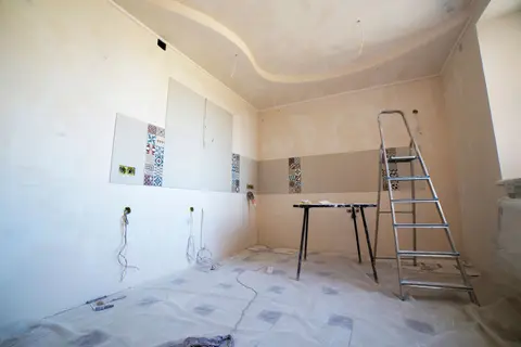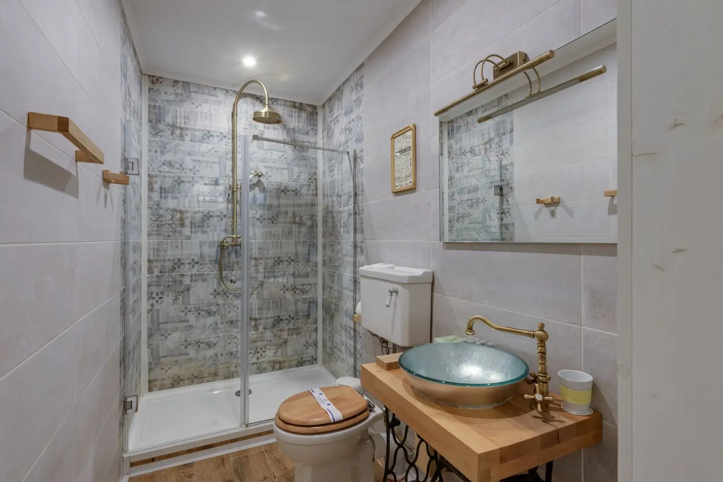
Fitting a bathroom suite is one of the more ambitious DIY projects, but for a competent homeowner it is entirely achievable, particularly a like-for-like replacement where the pipe positions and waste connections are already established. Where it gets complicated is when you are moving sanitary ware, adding a new shower, or installing in a new space, all of which bring in more complex drainage and electrical considerations.
This guide covers the full process, from planning and regulatory compliance to the step-by-step installation of a bath, basin, and toilet.
Planning and Preparation
What You Need to Decide First
Before purchasing any sanitary ware, confirm:
- Existing waste positions, the soil stack connection point determines where your toilet can go. Approved Document H shows an unventilated 100 mm branch of up to 6 m for a single close-coupled toilet, and up to 15 m where several WCs share the branch, laid at a fall of 18 to 90 mm per metre; a longer run needs a vent pipe or an air admittance valve.1 Moving a toilet away from the existing soil connection adds significant cost.
- Water supply type, do you have mains-pressure hot and cold (combi boiler), or a stored hot water system (cylinder)? This determines which taps and shower fittings are compatible.
- Room size and Part M, Approved Document M applies to newly built homes and to homes undergoing a material alteration, not to replacing a suite in an existing bathroom.2 For a new home’s entrance-storey WC it shows a clear access zone 750 mm deep in front of the pan, which is a sensible target in any bathroom.2
- Ventilation, Approved Document F sets an intermittent extract rate of 15 l/s for a bathroom, whether or not the room has an openable window.3 Where there is no openable window, the fan must also run on for at least 15 minutes after the room is vacated.3 When you refurbish an existing bathroom, keep or replace any extract fan that is already there.3 A new bathroom or en suite added to an existing home needs extract ventilation.3 Wiring the fan is notifiable under Part P only if it needs a new circuit or the work falls within the special location around the bath or shower.4
Tools and Materials
| Item | Typical cost |
|---|---|
| Adjustable spanners × 2 | £18–£30 |
| Basin wrench | £15–£25 |
| Pipe cutter (15 mm, 22 mm) | £12–£20 |
| PTFE tape (3–4 rolls) | £3–£6 |
| Silicone sealant (sanitary grade) | £5–£10 per tube |
| Flexible tap connectors (× 4) | £8–£16 |
| Push-fit fittings, waste trap kits | £40–£80 |
| Water isolation valves (× 4 min.) | £12–£20 |
Step-by-Step: Fitting the Bath
1. Fit the Bath Legs and Frame
Assemble the bath frame (if a steel/acrylic bath with a pressed steel frame) on the floor, then invert the bath to attach the leg cradle with the supplied brackets. Adjust the legs so the rim is level and at the height the bath panel and the maker’s instructions call for.
2. Fit the Taps and Waste Before Installing the Bath
This is the most important advice for any bath installation: fit all taps, overflow, and waste trap assembly before the bath goes in. Lying on your back under a fitted bath to tighten tap backnuts is miserable. Fitting them on the floor with the bath accessible is straightforward.
- Fit tap tails into the holes with rubber gaskets and backnuts. Tighten firmly with a basin wrench, do not overtighten on acrylic or fibreglass; hand-tight plus a half turn is usually sufficient.
- Attach the overflow pipe and bath waste. Use plumber’s putty or the supplied rubber seal under the waste flange.
- Fit the trap. Approved Document H gives a 40 mm trap with a water seal of at least 50 mm for a bath; a deeper 75 mm seal trap is fine if there is room under the bath.1
3. Position the Bath and Connect Waste
Slide the bath into position. The waste outlet must align with the existing 40 mm waste pipe in the floor or wall. Use flexible waste pipe if the alignment is not perfect, rigid ABS pipe requires exact positioning.
Connect the trap to the waste run with a slip-joint or push-fit fitting. Ensure there is a fall towards the drain (minimum 18 mm per metre for 40 mm horizontal waste runs under Part H of the Building Regs).1
4. Connect the Water Supply
Turn off the water at the mains (or at the isolation valves if already fitted). Solder or push-fit new isolation valves into the existing hot and cold supplies. Connect flexible tap connectors from the isolation valves to the tap tails, these allow the tap to be independently isolated for future maintenance.
Turn the water on slowly and check for leaks at every connection.
5. Seal the Bath
Once the bath is in its final position and tiled (or panels fitted), apply a continuous bead of white sanitary silicone along the joint between the bath rim and the wall. Smooth with a wet finger or proprietary tool. Allow 24 hours before use.
Step-by-Step: Fitting the Toilet
WC Pan
- Position the pan over the soil pipe connection. For a close-coupled or back-to-wall toilet with a horizontal or bottom outlet, use a pan connector to mate the pan outlet to the 110 mm soil pipe.
- Mark the fixing holes. Drill into the floor (use appropriate fixings for concrete screed or timber floor). Do not overtighten, cracked WC pan bases are a common and expensive mistake.
- Push the pan connector onto the soil pipe outlet.
Cistern
For a close-coupled cistern:
- Drop the internal siphon/dual-flush mechanism into the cistern.
- Secure the cistern to the pan using the long bolts and rubber washers provided, rubber washers must seat correctly to prevent the cistern rocking (which will cause leaks).
- Connect the 15 mm cold water supply with an isolation valve and flexible connector to the bottom-entry or side-entry inlet valve.
Test flush several times and check all connections.
Step-by-Step: Fitting the Basin
- Fit taps and waste pop-up mechanism (if applicable) before mounting the basin.
- Fix the pedestal to the floor (1 screw through the back foot is usually sufficient for stability).
- Lower the basin onto the pedestal and check it sits level.
- Mark and fix the basin to the wall using the supplied screws and appropriate wall plugs.
- Connect waste trap (32 mm for basin) to existing waste pipe with push-fit fittings.1
- Connect water supply with isolation valves and flexible connectors.
- Seal the joint between basin and wall with sanitary silicone.
Cost Summary
| Scenario | Typical cost (2026, inc. VAT) |
|---|---|
| DIY like-for-like suite replacement (materials only) | £350–£900 |
| Plumber labour, like-for-like replacement (2 days) | £600–£1,400 |
| Full bathroom renovation (suite + tiling + floor, plumber + tiler) | £4,500–£9,000 |
| Full bathroom renovation with new layout (moving soil stack) | £7,000–£14,000 |
What Requires a Professional
| Work | Qualification required |
|---|---|
| Mains water connections, pipework | DIY-legal; the work and every fitting must meet the Water Supply (Water Fittings) Regulations 1999, and WRAS-approved products are the usual way to show a fitting complies |
| New or relocated electrical circuits | Notifiable under Part P: a registered electrician self-certifies, or you notify building control before work starts |
| Extractor fan wiring to light switch | Notifiable under Part P only within the special location round the bath or shower, or if a new circuit is needed |
| Electric shower installation | Usually needs a new circuit, so notifiable under Part P; the shower must also meet the Water Fittings Regulations |
| Moving the soil stack connection | Best done by a qualified plumber; notifiable under Part H if creating a new drain connection |
Replacing a WC (with one that uses no more water), basin, bath or shower is not notifiable in England, provided the job includes no work to underground drainage and no change to the water supply or above-ground drainage that could affect health or safety.5 Adding a new bathroom is notifiable, although an installer registered with a competent person scheme can self-certify it where no shared or underground drainage is involved; otherwise notify Building Control before work starts.6 Notifiable electrical work must be done by a registered electrician who self-certifies it, or notified to building control before it begins.4 Any plumbing you do yourself must still meet the Water Supply (Water Fittings) Regulations 1999, which require every fitting to be installed in a workmanlike manner.7
References (7)
Figures in this note were checked against the sources below on 30 September 2026. Superscript numbers in the text point to them. Every source the site cites, by topic.
- 1technicalvery strongMinistry of Housing, Communities and Local Government.RN-SM6TRWThe statutory source for soakaway design and the discharge hierarchy every garden drainage note should state. Requirement H3(3) lists the order of priority for rainwater discharge: (a) an adequate soakaway or other adequate infiltration system, or where not reasonably practicable (b) a watercourse, or where not reasonably practicable (c) a sewer. Paragraph 3.25 bars infiltration devices within 5 metres of a building or road, in ground where the water table reaches the bottom of the device at any time of year, too close to other drainage fields or soakaways, or where contamination could pollute groundwater. Paragraph 3.26: soakaways serving less than 100 square metres are generally square or circular pits filled with rubble or lined with dry-jointed masonry or perforated ring units. Paragraph 3.27: design to a return period of once in ten years, and for small soakaways serving 25 square metres or less a design rainfall of 10mm in 5 minutes may be assumed as the worst case. Paragraph 3.28 requires percolation tests to derive the infiltration rate, and paragraph 3.30 sends larger soakaways to BS EN 752-4 or BRE Digest 365 Soakaway design. Paragraphs 2.10 to 2.12 cover pervious paving over a granular storage reservoir and warn against its use where sediment or oil spillage would block the pores. For foul drainage, paragraph 2.33 sets a minimum 75mm internal diameter, or 100mm for a WC, and Table 6 gives minimum gradients of 1 in 40 for 75mm and 100mm at peak flows under 1 litre per second.
- 2technicalvery strongMinistry of Housing, Communities and Local Government.RN-5IVIKFParagraph 1645 of the M4(2) guidance requires a minimum 1,200 mm clear space in front of and between all kitchen units and appliances in living, kitchen and eating areas. Wall switches, socket outlets, stopcocks and controls must have their centre line between 450 mm and 1,200 mm above floor level (Diagram 1.5), consumer units are mounted with switches 1,350 to 1,450 mm above floor level, and boiler timer controls and thermostats between 900 mm and 1,200 mm. Communal approach routes and flights need a minimum clear width of 1,200 mm and every landing a minimum 1,200 mm clear of any door swing. Handrail guidance is measured 450 mm above the pitch line of the treads.
- 3technicalvery strongMinistry of Housing, Communities and Local Government.RN-QD1SFFTable 1.1 sets minimum intermittent extract rates: kitchen with a cooker hood extracting outside 30 l/s, kitchen without one 60 l/s, utility room 30 l/s, bathroom 15 l/s, sanitary accommodation 6 l/s. Extract terminals and fans other than cooker hoods should be as high as practicable and no more than 400mm below the ceiling; a cooker hood should sit between 650mm and 750mm above the hob if the manufacturer gives no figure. Table 1.7 requires background ventilators of at least 8000mm2 equivalent area in habitable rooms and kitchens for a dwelling, 10,000mm2 for a single-storey dwelling. Background ventilators should be at least 1700mm above floor level and at least 500mm from a fan in the same room. On replacement windows, paragraph 3.14 says new windows must carry background ventilators no smaller than the originals, and paragraph 3.15 gives the fallback minimums where the old size is unknown: 8000mm2 habitable rooms, 8000mm2 kitchen, 4000mm2 bathroom. Paragraph 3.32 confirms that replacing an extractor fan or cooker hood on existing cabling is not notifiable.
- 4technicalvery strongMinistry of Housing, Communities and Local Government.RN-JYJ3I5The document that decides what electrical work a homeowner may legally do themselves, and the exact list of notifiable jobs. Regulation 12(6A), reproduced at paragraph 2.5, makes only three things notifiable: the installation of a new circuit, the replacement of a consumer unit, and any addition or alteration to existing circuits in a special location. Regulation 12(9) defines special location as, in a room containing a bath or shower, the zone extending vertically from finished floor level to 2.25 metres (or the shower head position if higher) and horizontally 600mm from the edge of the bath tub or shower tray. Paragraph 2.7 states that all other electrical installation work is not notifiable, namely additions and alterations to existing installations outside special locations, and replacements, repairs and maintenance anywhere. Paragraph 2.8 gives worked examples: a built-in cooker is not notifiable unless a new cooker circuit is needed, and connecting an electric gate or garage door to an existing isolator is not notifiable but running a new circuit from the consumer unit to that isolator is. Paragraph 2.2 confirms Part P reaches outdoor work including fixed garden lighting, pond pumps and outbuildings such as sheds, detached garages and domestic greenhouses. Notifiable work must be certified by self-certification by a registered competent person, third-party certification, or a building control body (paragraph 3.1), with the compliance certificate issued within 30 days (paragraph 3.4). Note that Approved Document P is a source of guidance rather than a ban: non-notifiable work still has to comply with BS 7671.
- 5technicalvery strongThe National Archives (legislation.gov.uk), guidance.RN-CC1O5HSchedule 4 lists building work that needs no building notice; item (g) covers a self-contained fixed service that is not a combustion appliance other than a fixed flueless gas cooker, so a flueless hob is exempt but flued appliances are not.
- 6technicalvery strongThe National Archives (legislation.gov.uk), guidance.RN-BP3IWGSchedule 3 item 12 lets registered installers (APHC, BESCA, Certsure, HETAS, NAPIT) self-certify sanitary installations in a dwelling that involve no shared or underground drainage.
- 7technicalvery strongThe National Archives (legislation.gov.uk), guidance.RN-8FEFU5Regulation 4 of the Water Supply (Water Fittings) Regulations 1999 as it applies in England and Wales. It requires every water fitting to be of an appropriate quality and standard and suitable for its use.
-
Approved Document H, Drainage and waste disposal, 2002 edition incorporating 2010 and 2015 amendments, Ministry of Housing, Communities and Local Government, accessed 14 September 2026. assets.publishing.service.gov.uk
-
Approved Document M, Access to and use of buildings, Volume 1: Dwellings, 2015 edition incorporating 2016 amendments, Ministry of Housing, Communities and Local Government, accessed 14 September 2026. assets.publishing.service.gov.uk
-
Approved Document F, Ventilation, Volume 1: Dwellings, 2021 edition, Ministry of Housing, Communities and Local Government, accessed 30 September 2026. assets.publishing.service.gov.uk
-
Approved Document P, Electrical safety: Dwellings, 2013 edition incorporating 2010 and 2013 amendments, Ministry of Housing, Communities and Local Government, accessed 30 September 2026. assets.publishing.service.gov.uk
-
The Building Regulations 2010, Schedule 4: Descriptions of work where no building notice or deposit of full plans required, legislation.gov.uk (The National Archives), accessed 30 September 2026. legislation.gov.uk
-
The Building Regulations 2010, Schedule 3: Self-certification schemes and exemptions from requirement to give building notice or deposit full plans, legislation.gov.uk (The National Archives), accessed 30 September 2026. legislation.gov.uk
-
The Water Supply (Water Fittings) Regulations 1999, regulation 4: Requirements for water fittings etc., legislation.gov.uk (The National Archives), accessed 30 September 2026. legislation.gov.uk