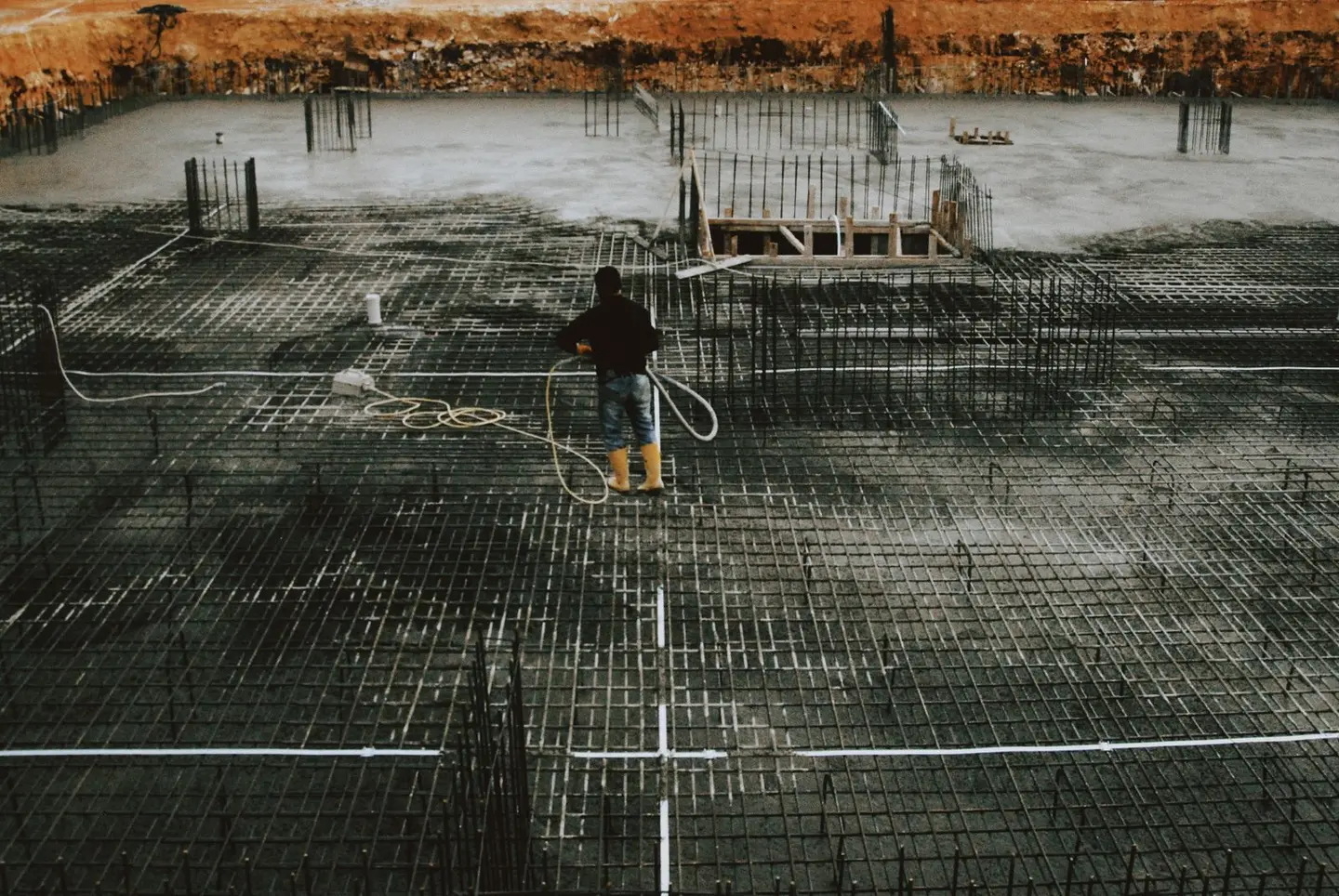
The foundation transfers building loads safely into the ground. Choosing the wrong type is one of the most expensive mistakes in construction, and one that Building Control will catch before the concrete is poured. In England, foundation design falls under Part A of the Building Regulations; Approved Document A gives simple rules for plain concrete strip foundations and refers to BS EN 1997-1 (Eurocode 7) for geotechnical design.1 NHBC Standards Chapter 4 is also widely used for domestic work, although Approved Document A does not refer to it.
Which type you need depends primarily on ground conditions (soil bearing capacity, presence of trees, made ground), building loads, and depth to firm strata. A soil investigation or at minimum a visual assessment of trial pits is essential before committing to a foundation type.
Strip vs Trench-Fill vs Raft vs Pile
These four types cover the vast majority of domestic and small-scale commercial work in the UK.
| Foundation Type | Typical Use | Concrete Commonly Specified | Approx Cost (2026) |
|---|---|---|---|
| Strip (traditional) | 2–3 storey domestic on firm ground | C25 | £150–£250/m run |
| Trench-fill | Domestic where labour is costly or clay is present | C25–C30 | £180–£320/m run |
| Raft | Poor/variable ground, extensions on soft fill | C30 | £80–£150/m² |
| Mini-piles + ground beam | Made ground, high trees, very poor bearing capacity | C30–C35 | £1,000–£3,000/pile + ground beam (rough guide) |
Costs include excavation and concrete but exclude any sub-base, DPM or insulation above foundation level. The concrete grades are what engineers commonly specify, not legal minimums: for plain concrete strip and trench-fill foundations in non-aggressive ground, Approved Document A accepts grade ST2 or GEN 1 concrete to BS 8500-2.1
Strip Foundations
The strip foundation is the UK default for domestic walls on reasonable ground. The strip is a continuous concrete pad running under every load-bearing wall, wider than the wall it carries, distributing load across a greater area of ground.
Typical dimensions:
- Width: wall thickness + 150 mm each side minimum, and LABC Warranty asks for at least 600 mm under external walls; a structural engineer or Building Control may require wider on weak ground2
- Thickness: at least 150 mm, or the projection P from Table 10 if that is greater; in practice often 225–300 mm1
- Minimum depth (ground level to the underside of the foundation): 0.45 m to avoid frost, except on rock; on shrinkable clay at least 0.75 m, 0.9 m or 1.0 m for low, medium or high shrinkage clay, and deeper near trees1
Minimum strip widths that need no calculation are given in Approved Document A Table 10, by ground type and wall load: on medium dense gravel or sand carrying up to 40 kN per metre of wall, the minimum width is 400 mm; on soft clay it is 650 mm for wall loads up to 30 kN/m, and Table 10 does not cover heavier loads on soft ground.1 These are conservative presumptive values; a structural engineer can justify narrower widths using Eurocode 7 calculations.
Concrete volume example: A 20 m perimeter house extension, 300 mm deep × 600 mm wide strip ≈ 3.6 m³ of concrete, which one ready-mix delivery can handle, although some suppliers add a part-load charge for small orders.
Trench-Fill Foundations
Trench-fill fills the excavated trench with concrete to within 150 mm of ground level, eliminating blockwork footings below DPC. This is now the more common approach in the UK because:
- Labour costs for bricklaying below ground are high
- It is faster: the trench is filled with concrete as soon as it has been dug and inspected, so it stays open for less time
- It suits shrinkable clay, where foundations have to go deep: a deep, narrow trench is simply filled with concrete rather than built up in masonry, although where nearby trees push the depth past 1.5 m, heave protection is needed2
Typical dimensions:
- Width: at least 600 mm under external walls, often 600–700 mm to suit the digger bucket2
- Depth to bottom of concrete: at least 0.75 m, 0.9 m or 1.0 m in low, medium or high shrinkage clay (Approved Document A)1
- Near high-water-demand trees such as oak, poplar and eucalyptus the required depth can reach 2.5 m; beyond that the foundation must be designed by a chartered structural engineer, and short bored piles are usually the answer2
Concrete volume example: The same 20 m perimeter at 700 mm wide, 1.0 m deep fill = 14 m³. At £105/m³ (C25 delivered), that is approximately £1,470 in concrete alone, nearly four times the strip’s concrete, but the labour saving on below-ground blockwork typically offsets this on most sites.
Engineers commonly specify C25 to C30 or a designated foundation mix for trench-fill, ordered at a high workability so that it flows and levels in the trench without vibration.
Raft Foundations
A raft is a reinforced concrete slab covering the entire building footprint, distributing load across a wider area. Rafts are usually designed for ground with low bearing capacity or pockets of fill, and are worth considering where:2
- Ground bearing capacity is low or variable (soft silts, made ground, uneven demolition fill)
- Differential settlement risk is high
- A suspended ground floor is needed anyway and combining raft + floor makes structural and economic sense
Typical specification:
- Slab thickness: 250–400 mm for domestic; thickened edge beams (often 500–600 mm deep × 600 mm wide) under load-bearing walls
- Grade: typically C30, reinforced to the engineer’s design, commonly with A252 mesh or heavier in the slab and bars such as T16 in the edge beams
- Insulation: typically 100 mm or more of PIR, or a thicker layer of EPS, under the slab to meet Part L, whose limit for a new dwelling floor is 0.18 W/m²K; 0.13 is the notional dwelling figure a design is usually taken towards3
Raft design should always be checked by a structural engineer: the reinforcement layout is critical to preventing punching shear failure and differential cracking. Building Control and warranty providers will require calculations.2 LABC Warranty does not accept a raft where the ground is liable to heave or shrinkage, for example where trees are present or have been removed.2
Piled Foundations
Piling is specified when the depth to firm strata exceeds the economic limit for trench-fill, which LABC Warranty puts at about 2.5 m, or where trees make shallow foundations unworkable.2 Mini-piles (150–300 mm diameter CFA or driven steel tube) are common in domestic work.
Typical domestic piling:
- Pile diameter: 150–250 mm CFA (continuous flight auger)
- Pile spacing: 1.5–2.5 m centres depending on load
- Pile depth: 5–12 m to reach firm stratum (London Clay: often 8–10 m)
- Ground beam: 400–600 mm deep × 300 mm wide RC connecting pile heads
Piling cost varies enormously with depth, rig access and how many piles share the cost of bringing the rig to site, so treat any figure as a rough guide until a specialist has quoted. As a very rough budget, allow £1,000–£3,000 per pile installed on a small domestic job, plus the RC ground beam at roughly £200–£350/m run. A six-pile scheme for a modest rear extension with about 15 m of ground beam can therefore cost in the region of £9,000–£24,000 before the superstructure begins, making geotechnical investigation before design essential.
Depth and Building Regulations
Approved Document A (2004, amended 2013) and its supporting tables give presumptive foundation sizes for domestic work, but these are subject to:
- Frost depth, at least 0.45 m from ground level to the underside of the foundation, except on rock, and more where frost lasts for long periods1
- Shrinkable clay depth, at least 0.75 m, 0.9 m or 1.0 m for low, medium or high shrinkage clay under Approved Document A; near trees, NHBC Chapter 4.2 adds depth according to the clay’s volume change potential and the tree’s water demand, height and distance, and anything beyond 2.5 m needs an engineer’s design1
- Adjoining structures and drains, a new foundation next to an existing one is usually taken down so that neither loads nor undermines the other. Under Approved Document H, a drain trench should not be dug lower than the foundations of a nearby building unless it is filled with concrete: up to the foundation’s underside where the trench is within 1 m, and further away to a level below the foundation equal to the trench’s distance from the building, less 150 mm.4
Building Control will usually want to see a trial pit, assessed by the engineer or the building control surveyor, and a geotechnical report for anything other than straightforward conditions. NHBC Chapter 4.1 specifies the investigation requirements for new homes.
Key Standards
- Approved Document A (Structure), Section 2E for domestic foundations; Table 10 for presumptive widths1
- BS EN 1997-1:2004+A1:2013 (Eurocode 7), geotechnical design; used by structural engineers for calculated designs5
- BS 8004:2015, code of practice for foundations6
- NHBC Standards Chapter 4.2 (building near trees) and Chapter 4.3 (strip and trench fill foundations), widely accepted by Building Control
- BRE Special Digest 1 (SD1), Concrete in aggressive ground: Approved Document A points to it, with BS 8500-1, for foundations in chemically aggressive soil; it classifies the ground by design sulfate class and sets the concrete needed for each1
Always commission a structural engineer to design foundations for extensions of any significance: HomeOwners Alliance puts a structural engineer’s input on a loft conversion or extension at £750–£2,200 in 2026, which is small against the cost of putting right under-designed foundations.7
The rules in this note are those that apply in England. Scotland, Wales and Northern Ireland have their own building standards and permitted development rights.
References (7)
Figures in this note were checked against the sources below on 2 October 2026. Superscript numbers in the text point to them. Every source the site cites, by topic.
- 1technicalvery strongMinistry of Housing, Communities and Local Government (GOV.UK).RN-Z6AXUWThe full Approved Document A PDF, which carries the deemed-to-satisfy tables a domestic project is checked against. Section 2E covers foundations of plain concrete: paragraph 2E3 gives the recommended minimum widths of strip foundations in Table 10, keyed to ground type and total load of loadbearing walling per linear metre. Table 10 sets, for rock (not inferior to sandstone, limestone or firm chalk, requiring at least a pneumatic or mechanically operated pick to excavate), a width equal to the width of the wall at every load. For medium dense gravel or sand (requires a pick to excavate, a 50mm square wooden peg hard to drive beyond 150mm) and for stiff clay or stiff sandy clay (can be indented slightly by the thumb), the minimum widths are 250mm at 20 kN per linear metre, 300mm at 30, 400mm at 40, 500mm at 50, 600mm at 60 and 650mm at 70. Firm clay and firm sandy clay (thumb makes an impression easily) start at 300mm. The document also covers minimum depth of strip foundations, wall thickness rules for residential buildings up to three storeys (paragraph 2C10 covers internal loadbearing walls in brickwork or blockwork), buttressing, lateral support by floors and at roof level, interruption of lateral support, wall cladding in Section 3, and Section 5 on reducing sensitivity to disproportionate collapse with the building consequence classes.
- 2technicalstrongLABC Warranty (MD Insurance Services Limited), guidance.RN-R25BHUWarranty provider technical requirements for foundations, covering mass fill, strip, piles, raft, engineered fill, vibratory ground improvement, and trees and clay. Key figures: all foundations must bear onto virgin stable subsoil with a minimum depth of 450mm from finished ground level to underside to avoid frost action; mass fill foundations must be a minimum 600mm wide for external walls, reducing to 450mm for single leaf internal walls up to 150mm thick, with a 150mm projection each side and the foundation centred under the wall; concrete filling to the cavity is kept a minimum 225mm below DPC. Low rise structures are designed so maximum settlement does not exceed 25mm, with a design limit for maximum tilt of 1/500. In cohesive soils with trees present: heave protection is required where foundation depth exceeds 1.5m, short bored piles with ground beams are recommended beyond 2m, and depths beyond 2.5m are outside the online foundation depth calculator and must be a piled engineered solution designed by a chartered structural engineer. Foundations must also be below the invert level of any adjacent drain or sewer.
- 3technicalvery strongMinistry of Housing, Communities and Local Government.RN-L0FCJXThe in-force U-value tables a DIY insulation or door note must quote, with the exact numbers. Table 4.2, limiting U-values for new fabric elements in existing dwellings, sets roof 0.15, wall 0.18, floor 0.18, swimming pool basin 0.25, window 1.4 or Window Energy Rating Band B minimum, rooflight 2.2, doors with more than 60 per cent of the internal face glazed 1.4 or Doorset Energy Rating Band C minimum, and other doors 1.4 or Doorset Energy Rating Band B minimum. Table 4.3, for existing elements, gives a roof threshold of 0.35 and an improved value of 0.16, which is the figure a loft insulation note needs: paragraph 4.12 says a retained element whose U-value is higher than the column (a) threshold, for example through a loft or garage conversion, should be upgraded to the column (b) value. Paragraph 4.13 allows a lesser upgrade only where the improved value is not technically or functionally feasible or would not achieve a simple payback of 15 years or less. Paragraph 4.8 requires a replacement element to be no worse than the one it replaces as well as meeting Table 4.2. Paragraph 4.10 gives the heritage exception: where character must be maintained, a centre pane U-value of no more than 1.2 or low-emissivity secondary glazing. Note 9 records that the timber window concession of 1.6 or Band C ended on 14 June 2023. The 2021 edition came into force on 15 June 2022; a 2026 edition exists at https://assets.publishing.service.gov.uk/media/69c122a6cfa346b9d4704a55/ADL1_2026.pdf.
- 4technicalvery strongMinistry of Housing, Communities and Local Government.RN-SM6TRWThe statutory source for soakaway design and the discharge hierarchy every garden drainage note should state. Requirement H3(3) lists the order of priority for rainwater discharge: (a) an adequate soakaway or other adequate infiltration system, or where not reasonably practicable (b) a watercourse, or where not reasonably practicable (c) a sewer. Paragraph 3.25 bars infiltration devices within 5 metres of a building or road, in ground where the water table reaches the bottom of the device at any time of year, too close to other drainage fields or soakaways, or where contamination could pollute groundwater. Paragraph 3.26: soakaways serving less than 100 square metres are generally square or circular pits filled with rubble or lined with dry-jointed masonry or perforated ring units. Paragraph 3.27: design to a return period of once in ten years, and for small soakaways serving 25 square metres or less a design rainfall of 10mm in 5 minutes may be assumed as the worst case. Paragraph 3.28 requires percolation tests to derive the infiltration rate, and paragraph 3.30 sends larger soakaways to BS EN 752-4 or BRE Digest 365 Soakaway design. Paragraphs 2.10 to 2.12 cover pervious paving over a granular storage reservoir and warn against its use where sediment or oil spillage would block the pores. For foul drainage, paragraph 2.33 sets a minimum 75mm internal diameter, or 100mm for a WC, and Table 6 gives minimum gradients of 1 in 40 for 75mm and 100mm at peak flows under 1 litre per second.
- 5technicalstrongBSI Knowledge, a standard.RN-XX7O5XBS EN 1997-1:2004+A1:2013, Eurocode 7 part 1, the general rules for geotechnical design: ground investigation, bearing resistance, settlement and retaining structures. Read with BS 8004, it is what a foundation design for an extension is justified against, including the case for going deeper next to a tree.
- 6technicalstrongBSI Knowledge, a standard.RN-OC1LE0BS 8004:2015+A1:2020, the code of practice for foundations, the main UK design standard for geotechnical and structural engineers on foundation design and construction. Behind every statement about minimum depth, bearing capacity, and the influence of trees and clay shrinkage on a foundation, which is the question an extension on a shrinkable clay site turns on.
- 7costfairHomeOwners Alliance, guidance.RN-6O3Y7XA price, true at 2026-09. HomeOwners Alliance on structural engineer costs in 2026, around £100 an hour, with typical fees for common jobs: calculations for a beam over a knocked-through wall, an extension design, a structural survey. A consumer body's figures, so treat the hourly rate as indicative and the list of what needs an engineer at all as the useful part.
-
Approved Document A: Structure, 2004 edition incorporating 2004, 2010 and 2013 amendments, HM Government (GOV.UK), accessed 7 September 2026. assets.publishing.service.gov.uk
-
Technical Manual Version 10, Section 3: Foundations, LABC Warranty, accessed 29 September 2026. labcwarranty.co.uk
-
Approved Document L: Conservation of fuel and power, Volume 1: Dwellings, 2021 edition incorporating 2023 amendments, HM Government (GOV.UK), accessed 7 September 2026. assets.publishing.service.gov.uk
-
Approved Document H, Drainage and waste disposal, 2015 edition, HM Government (GOV.UK), accessed 2 October 2026. assets.publishing.service.gov.uk
-
BS EN 1997-1:2004+A1:2013 Eurocode 7. Geotechnical design. General rules, BSI Knowledge, accessed 7 September 2026. knowledge.bsigroup.com
-
BS 8004:2015+A1:2020 Code of practice for foundations, BSI Knowledge, accessed 7 September 2026. knowledge.bsigroup.com
-
Structural Engineer Costs In 2026, HomeOwners Alliance, accessed 2 October 2026. Priced at 2026-09 and left there. hoa.org.uk